Example #R2eboot Device Constructed By Me
| All parts mounted
All parts are mounted on the board and partly connected to each other. | 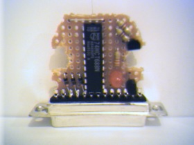 |
| Wiring port outputs to board
To make wiring as transparent as possible, wires carrying the signal to compare are mounted
on top of the board. Plug's D0-D7 is on this site too. | 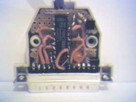 |
| Bottom view
All ground pins are short circuited on the plug to avoid hazzles with cables and/or plugs that
dont connect all of them. Later on there is going to be plenty of solder since the ground connection also
keeps plug and board together. (After reset cord has been attached.) | 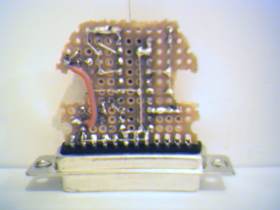 |
| Ready to use
Fully assembled and equipped with a long cord. Inside the cord itself is heavily soldered to ground pins
to prevent accidential pulls from rip it off - or worse - damage the device itself. | 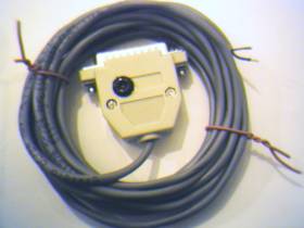 |