Frequency Counter and Timer
In counter mode it provides 1Hz resolution up to 100Mhz. In timer mode maximum resolution is 0.0000001 Hz up to 1Hz. Resolution is reduced by one digit for each additional decade. Multiple frequency updates per second by employing a sliding window for calculation.
Parts needed (including extensions):
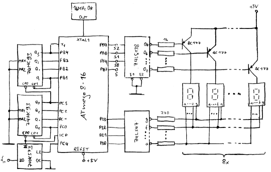
- 1 * AVR ATmega8 - micro controller
- 2 * 74HC93 - high speed cmos 4bit counter
- 1 * 74HC573 - high speed cmos latch
- 1 * 74LS47 - open collector bcd to 7 segment decoder
- 2 * 74LS138 - 3 to 8 multiplexer
- 1 * 16MHz Crystal Oscillator - or 1 or 4 MHz, see below
- 8 * BC177 - or any pnp suitable to drive up to 7 LEDs
- 4 * ODR-204 - (2 digits each) or any 7 segment LEDs with common anode
- 7 * 1N4001 - or any other diode
- 8 * 1kOhm 1/4W
- 8 * 220Ohm 1/4W
- 4 * 47kOhm 1/4W
Extensions
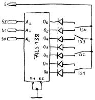
This switch interface provides 7(8) additional input bits at the cost of only one Mega8 pin.The inputs are used for mode control switches as followes:
- IS1: input select (for prescaler compensation)
- IS2: method select (counter, auto, timer)
- IS3: display select (frequency or duration)
- IS4: reserved for future extensions
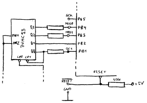
In case the AVR should be programmable in circuit, a few modifications must be made. In essence all third parties on wires used for programming are isolated using 47k resistors.
The resistors in combination with Mega8 gate capacity create a low pass. This is software compensated using increased settling time for the external counter.
Pictures
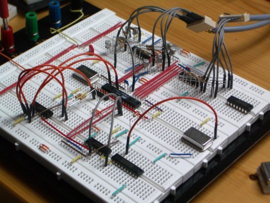
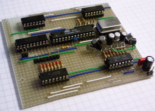
This picture shows the test board with the full counter circuit except the 7 segment LEDs. Those are already mounted and soldered on a separate board. The wires on the top right connect to it. (One connector for digit selection and one for the actual 7 segment code.)
The crystal osciallator in the bottom right corner is for testing circuit and software.
This is the final board that will be put into the device. It has connectors for power, 7 segment code, digit selection, in circuit programming and TTL signal input.
Board size is defined by the case so the BC177s are mounted somewhat tight.
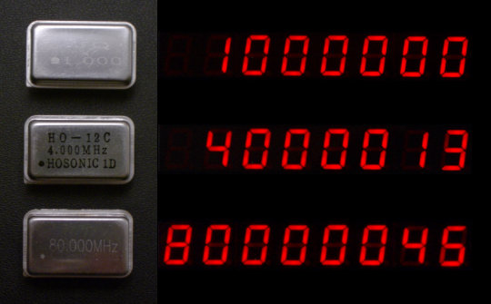
Some precision testing.
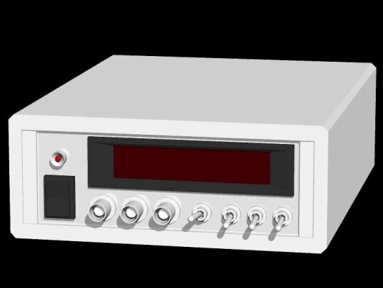
3d model of the front panel layout.
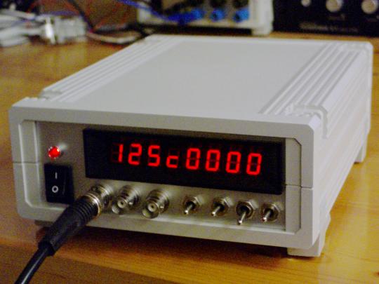
Only TTL input at this point but working. The "c" represents the comma in high precision timer mode.
License
Files found in the downloadable archives below are released under the GNU GPL.
Downloads
Firmware 0.0.2 Source & Intel Hex
Beautiful but where can i find a cao view of the schematic?
Sehr schnes Projekt. Allerdings arbeitet es bei mir nicht mit der hex-Dtei. Mu ich den Source-Code komplett bersetzen und womit ? AVR-Studio stolpert ber die Datei iom16.h :(
Gre, Jarod
I used avra for assembly and sp12 for programming the Atmel. HTH
Hi michael,
Very nice project! I'm also designing my ownn frequency counters based on PIC µC programmed in Pascal. Could you give more information about your sliding window? Basically I suppose you are using a 1 second gate in order to obtain 1Hz resolution, and this time counter is made by software? But how did you setup a sliding window based on this ? Is your time counter running permanently and you read the freq count many times per sec but calculate the freq count on 1s sliding window ? How Thanks for your explanations
Hallo, klasse Z¤hler. Endlich jemand, der der Versuchung widersteht, die Timer des ATmega zu nutzen. Z.Z. bertrage ich die handschriftlichen Zeichungen nach Eagle. Dann hab ich die Pinbelegung im Schaltplan und kann leichter verdrahten. Dabei sind mir zwei Dinge aufgefallen:
1. Gibt es einen Grund, warum der freie Pin 28, PC5, nicht fr die Ansteuerung der Dezimalpunkte genutzt wird?
2. Der Pin 15, PB1 (OC1A), ist in der Skizze mit den Modifikationen fr den ISP-Anschlu mit einem 47k-Widerstand an den Hi-Nibble-Counter angeschlossen. OC1A ist aber am ISP-Anschlu gar nicht vorgesehen. Ist der Widerstand erforderlich und wenn ja, warum? (ich bin ja sooo neugierig ;-))
Danke fr das Projekt. Nach alter V¤ter Sitte hat jeder vernnftiger Z¤hler rote LEDs und 8 Stellen zu haben. Behaupte ich jedenfalls mal.
Gre - Rolf