FPGA VHDL Model
This page gives an overview of the "hardware" logic programmed into the FPGA. The actual VHDL source code can be found in the source package on the main page.
Top Level
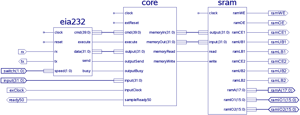
This schema lacks the display and clockman module. The display module is only for debugging and does nothing but to feed 'memoryOut' to the 4 digit 7 segment display using multiplexing.
The clockman module generates the 100MHz clock signal that is used throughout the system.
EIA232
Allows to communicate with the core using a EIA232/RS232 interface. The module (de-)serializes commands and data and handles the XON/XOFF commands, which - up to version 0.6 - were detected by the decoder (see core).
SRAM
Controls the external SRAM. (Address counter and control signals)
Core
The core contains all "platform independent" modules and provides a simple interface to those components. The core makes the analyzer memory type and computer interface independent.
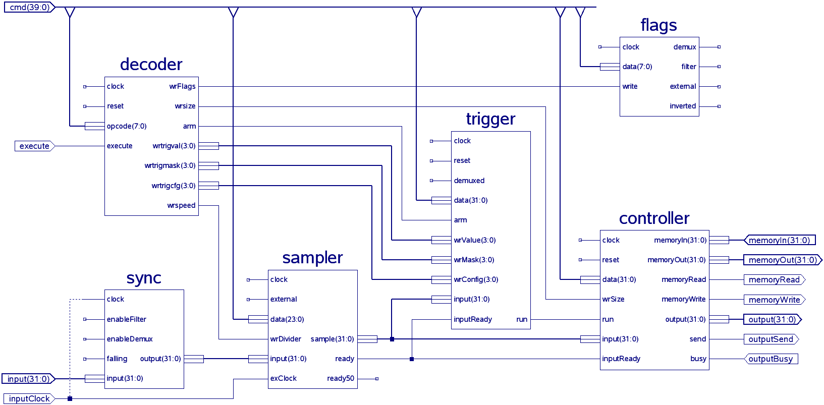
Some modules are missing in this schema: Trigger uses Stage internally. Sync uses Demux and Filter internally.
Controller
Controls the capturing & read back operation.
If no other operation has been activated, the controller samples data into the memory. When the run signal is received, it continues to do so for fwd * 4 samples and then sends bwd * 4 samples to the transmitter. This allows to capture data from before the trigger match which is a nice feature.
Note: Data read back from before the 'run' signal might be invalid if the controller configuration was changed recently and not enough data was gathered before the signal was set.
Decoder
Takes the opcode from the command received by the receiver and decodes it when 'execute' is set. The decoded command will be executed for one cycle.
The receiver keeps the cmd output active long enough so all the data is still available on its cmd output when the command has been decoded and sent out to other modules with the next clock cycle.
Demux
Demultiplexes 16 input channels into 32 output channels, thus doubling the sampling rate for those channels. (This module barely does anything anymore, but is kept for historical reasons.)
Filter
Fast 32 channel digital noise filter using a single LUT function for each individual channel. It will filter out all pulses that only appear for half a clock cycle. This way a pulse has to be at least 5-10ns long to be accepte as valid. This is sufficient for sample rates up to 100MHz.
Flags
Flags register. (The different flags and their meanings are described on the protocol page.)
Sampler
Produces samples from input applying a programmable divider to the clock. Sampling rate can be calculated by:
r = f / (d + 1)
Where r is the sampling rate, f is the clock frequency and d is the value programmed into the divider register.
As of version 0.6 sampling on an external clock is also supported. If external is set to '1', the external clock will be used to sample data. (Divider is ignored for this.)
Stage
Programmable 32 channel trigger stage. It can operate in serial and parallel mode. In serial mode any of the input channels can be used as input for the 32bit shift register. Comparison is done using the value and mask registers on the input in parallel mode and on the shift register in serial mode. If armed and 'level' has reached the configured minimum value, the stage will start to check for a match. The match and run output signal delay can be configured. The stage will disarm itself after a match occured or when reset is set.
The stage supports "high speed demux" operation in serial and parallel mode. (Lower and upper 16 channels contain a 16bit sample each.)
Matching is done using a pipeline. This should not increase the minimum time needed between two dependend trigger stage matches, because the dependence is evaluated in the last pipeline step. It does however increase the delay for the capturing process, but this can easily be compensated by software. (By adjusting the before/after ratio.)
Sync
Synchronizes input with clock on rising or falling edge and does some optional preprocessing. (See Filter and Demux above for more details.)
Trigger
Complex 4 stage 32 channel trigger.
All commands are passed on to the stages. This file only maintains the global trigger level and it outputs the run condition if it is set by any of the stages. (See Stage above for more details.)
BTW: Which application did you use to generate the Model Diagrams?
The Xilinx development tools can produce schematic diagrams like that.
In the process tree \"synthesis\" simpli double click on the process \"View RTL schematic\"